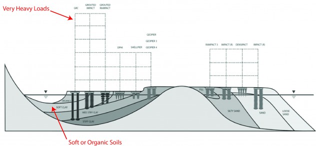
Geopier rigid inclusions consist of cement treated aggregate, grouted aggregate or concrete columns that are often used to transfer the stress from foundation or embankment loads through very soft soils down to stiffer soil or rock layers. While Geopier rigid inclusions can be specified as the singular solution for a project, they can also be used in combination with conventional Geopier Rammed Aggregate Pier ground improvement methods to optimize performance and costs.
When rigid inclusions are specified using a performance based specification you can allow for more innovation and cost savings versus restricting the use of a single method of construction. The following sections answer some of the main questions engineers and contractors have regarding rigid inclusions.
WHY USE RIGID INCLUSIONS
When Geopier Rammed Aggregate Pier elements cannot control settlement adequately in soft soils and you have a stiffer soil layer below the soft soils the use of Geopier Rigid Inclusions can usually solve the problem.
This can occur with moderate loads in profiles with peat or organic soil layers or heavy loads with thick soft silt or clay layers.
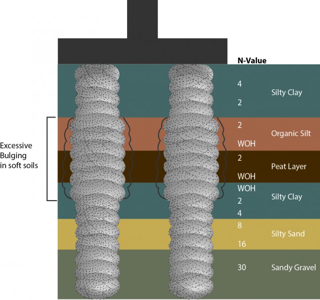
Geopier Rammed Aggregate Piers with excessive bulging in Organic layers
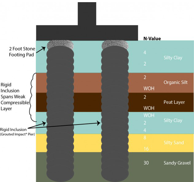
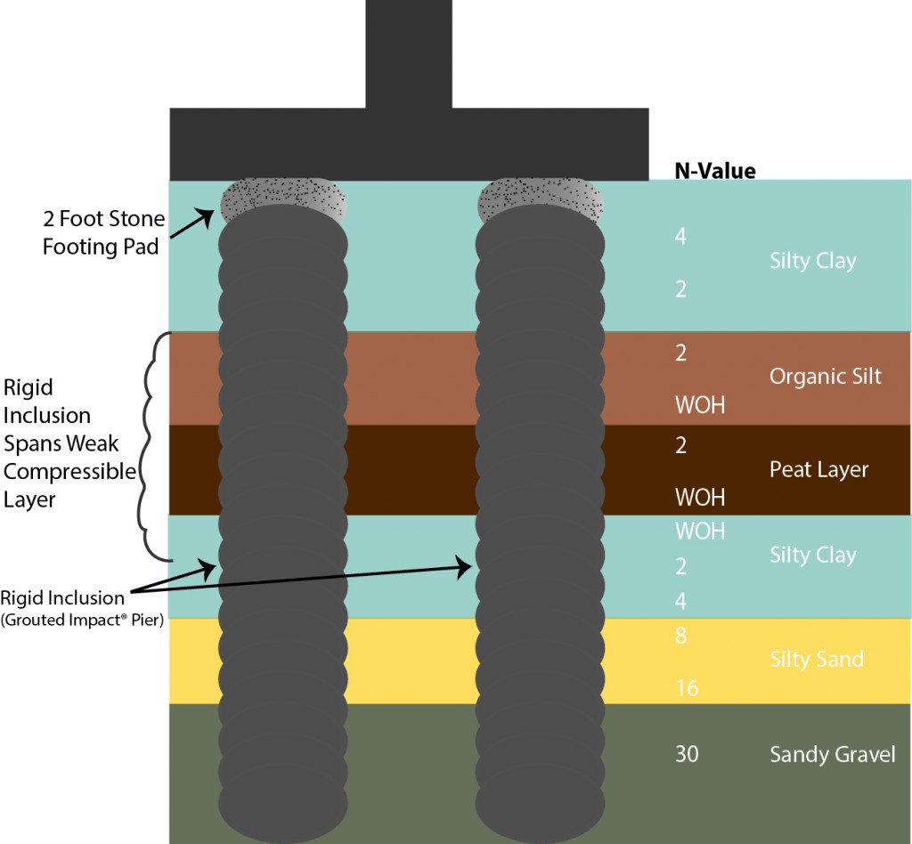
Rigid Inclusions used to span weak layers and are founded in a dense soil layer
WHAT IS A RIGID INCLUSION ?
They are stiff Ground Improvement elements that consist of aggregate mixed with cement or grout, or elements made of plain concrete. The elements are stiff enough to transfer the stress from a slab, footing or embankment load through soft soil layers down to a firm soil or weathered rock layer.
There are many ways to create a rigid inclusion. For the last 10 years GeoStructures has been using a variety of rigid inclusion elements to meet project requirements including:
■ CTA – cement treated aggregate compacted in Geopier GP3® elements
■ Cement Grouted #57 Stone – installed using Impact® Pier displacement technique
■ Cement/Sand Grout and # 57 Stone – installed in Impact Pier elements
■ GeoConcrete™ Columns installed using Impact Pier Displacement Technology
Rigid Inclusion Properties
■ High Compressive Strength – 500 psi to 6000 psi
■ High Stiffness
■ Diameters ranging from 15 to 36 inches
■ Capacities ranging from 75 kips to 350 kips
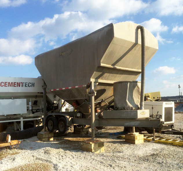
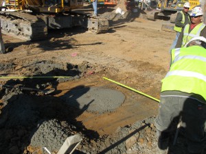
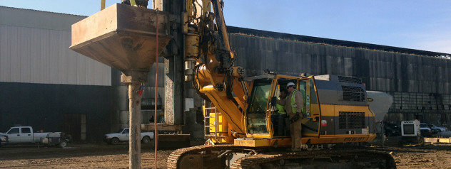
Cement Treated Aggregate (CTA) being mixed on a job site
Using a well graded No.21A type aggregate and 5% cement provides sufficient compressive strength for most rigid inclusion applications. Typical compressive strengths range from 500 to 1000 psi depending on the mix design and project requirements.
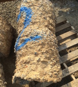
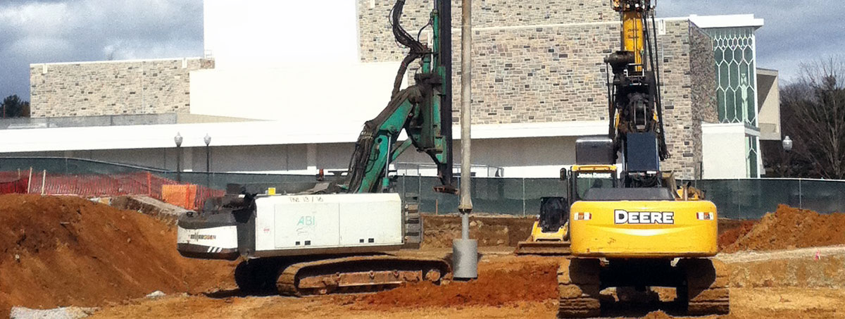
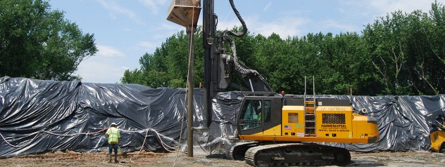
20 inch Diameter Grouted Impact Pier Elements
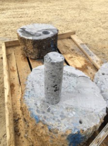
Using a sand-cement grout mixture results in unconfined compressive strength ranging from 3000 to over 6000 psi depending on the mix design.
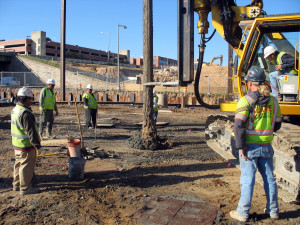
18 inch Diameter GeoConcrete Columns (GCC) being installed with a 36 inch cap
RIGID INCLUSION DESIGN PROCESS
The selection of the sizes and types of rigid inclusions to use on a project depends on the magnitude of loads being supported and the subsurface conditions. In general, the steps needed to design a rigid inclusion are as follows:
Structural Performance – The structural design capacity of a rigid inclusion is controlled by the unconfined compressive strength for the unreinforced Cement Treated Aggregate (CTA), grouted aggregate or concrete rigid inclusion being subjected to compressive loads. The design capacity of a rigid inclusion can be calculated using either a Load and Resistance Factor Design (LRFD) or an Allowable Stress Design (ASD) approach depending on the type of structure to be supported and the type of element to be used on the project. The capacity is typically about 30% of the unconfined compressive strength of the rigid inclusion material. The unconfined compressive strength of the element material can vary from typically 750 pounds per square inch (psi) for CTA to 1500 psi for neat cement grouted aggregate columns to over 4,000 psi for precision sand cement grouted or concrete columns. Steel reinforcements are typically not used when the rigid inclusion elements are being used for compression. The design capacity is rarely controlled by the unconfined compressive strength of the rigid inclusion. It is normally the geotechnical design for end bearing and skin friction that control the design.
Geotechnical Performance – The geotechnical capacity of a rigid inclusion is governed by the bearing capacity of the soil in which the rigid inclusion is founded. For example, for rigid inclusions in sand the capacity, q, could be calculated as follows:
q = q’ N ≤ q (Meyerhoff 1976)
Where:
q’ = effective vertical stress at the tip
N = Bearing capacity factor of the soil for driven displacement piles near the tip of the rigid inclusion.
For rigid inclusions in clay the geotechnical capacity, qp, is governed by the undrained shear strength of the clay
qp = Ssu Nc
Where:
su = Undrained shear strength
Nc= 9 = Bearing capacity factor for deep circular footings
Shaft skin friction may be considered when a rigid inclusion pier extends a minimum of 5 ft into a competent soil stratum. For this case, or one where piers extend through multiple soil strata below an unsuitable layer, a unit friction value can be computed for each layer, and the total shaft skin friction resistance can be taken as the summation of the individual layers. Skin friction should not be considered in fill materials. To provide relatively uniform footing support, a compacted crushed stone layer or rammed aggregate pier thickness is normally placed over the tops of the rigid inclusions beneath each footing. The purpose of the aggregate layer is to spread the load and provide a shear break should the footing be subject to lateral forces.
Note for projects where new grade raise area fills are being placed, the inclusions need to be designed for the new fill loading if installed before fill is placed, or settlement of the new fill needs to occur prior to rigid inclusion installation. Otherwise the rigid inclusions need to be designed for negative down drag loading.
Settlement Performance – Once the length, diameter and capacity of the rigid inclusion are defined, then the settlement of the system can be determined. Settlement is governed by compression of the crushed stone placed between the footing and the top of the rigid inclusion, the individual rigid inclusion elastic compression, and the compression of the soil below the rigid inclusions under the full footing load. Compression of the soil below the rigid inclusion is calculated using typical geotechnical settlement analyses.
Capacity and compression of the load transfer layer and the individual rigid inclusion is verified with a full scale load test generally following the procedures outlined in either ASTM D 1143 (static) or D 7383 (dynamic)(Statnamic).
APPLICATIONS FOR RIGID INCLUSIONS
Some of the common problems being solved with Geopier rigid inclusions and combinations of Geopier rigid inclusions and conventional Rammed Aggregate Pier® (RAP) elements include:
■ Isolating Stress from Heavily Loaded Footings
■ Supporting Heavily Loaded Mats and Slabs
■ Spanning Organic and Peat Layers
■ Providing Foundation Support Adjacent to Below Grade Structures
ISOLATING STRESS FROM HEAVILY LOADED FOOTINGS
High Column Loads which Stress Adjacent Footings
Problem: The high stress applied by heavily loaded footings on adjacent footings can result in excess footing settlement causing unsatisfactory total and differential settlement between footings.
Solution: By founding the heavily loaded footings on Rigid Inclusions the stress from these footings can be isolated and transferred down to dense soils or weathered rock, while the smaller footings can be founded on shallow RAP elements. The combination provides a more economical solution since lightly loaded footings can be supported by less expensive Rammed Aggregate Pier elements when not influenced by the adjacent stresses from the heavily loaded footings supported by rigid inclusions.
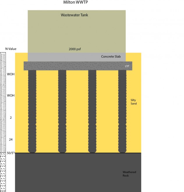
SUPPORT OF HEAVILY LOADED MATS AND SLABS
Problem: Heavily loaded mat foundations for building or tanks and heavily loaded slab foundations sometime require the use of stiffer pier elements to control total and differential settlement.
Solution: The use of Geopier Rigid Inclusions founded in dense or hard soil profiles or rock can often be the most efficient ground improvement technique. The key to transferring the load into the pier is in the design of the load transfer layer or mattress. For low capacity rigid inclusions often times a 1 to 2 ft rammed aggregate pier layer placed on top of the rigid inclusion can control the stress transferred into the slab or mat. As the capacity and spacing of the rigid inclusion increases it may be necessary to provide a gravel mattress.
SPANNING ORGANIC SOIL OR PEAT LAYERS
Problem: Consolidation of organic layers and or layers of Peat can result in excess settlement of shallow foundations and floor slabs.
Solution: The use of Geopier Rigid Inclusions or Rigid Inclusion zones within a Rammed Aggregate Pier can control settlement of the foundation while minimizing stress in the organic or peat layer. Because the foundation stress is transferred directly into the Rigid Inclusion to a stiffer layer, settlement of the foundation is controlled by the soil properties below the organic or peat zone.
The use of Rigid Inclusion zones on top of rammed aggregate pier elements can also be used to dramatically reduce the cost of ground improvement versus 100% rigid inclusions.

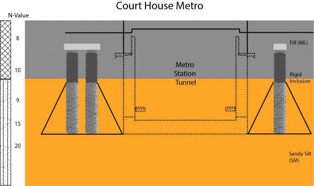
FOUNDATION SUPPORT ADJACENT TO BELOW GRADE STRUCTURES
Problem: The use of shallow foundations directly adjacent to structures with below grade walls, utilities or tunnels must consider the stress imposed by the footing on the structure or the footing needs to be lowered to below the zone of influence.
Solution: Shallow footings supported by a Rigid Inclusion or combination of a Rigid Inclusion atop a standard Rammed Aggregate Pier (RAP) have been shown to be a viable solution. By lowering the elevation at which the footing stress bears to an elevation below the zone of influence for the structure, the problem is easily solved.

SPECIFYING RIGID INCLUSIONS
For projects where the foundation support is provided using a design-build delivery system it is always better to provide a specification that defines performance requirements versus a specification that defines how a system is to be installed. By using a performance specification you allow for more innovation and cost savings versus restricting the use a single method of construction. The key items that a performance specification should include are:
Pre-Qualified Bidders
Bonding Capacity
General and Professional Liability
Project Experience
Previous Experience on Similar Size Projects
In House Design and Construction Experience
Technical Performance Criteria
Structural
Geotechnical
Settlement