GROUND IMPROVEMENT
■ Rapid Impact Compaction Technology FAQs
Geopier Rammed Aggregate Pier® (RAP) systems consist of a very stiff, vertically rammed, compacted aggregate shaft placed within the soil needing improvement. The high-energy impact compaction imparted on the aggregate within the Geopier element also produces significant lateral pre-straining and pre-stressing of the adjacent matrix soils. The lateral stress in the matrix soil surrounding the Geopier element approaches Kp, the coefficient of passive earth pressure. This means that the lateral stresses of the soil can be as much as 2 to 3 times greater than originally imparted by the soil. Due to this high degree of vertical compaction and lateral confinement, the Geopier element provides stiffness that can control settlement of structures very efficiently.
GP3 and Impact systems are alternatives to overexcavation and replacement of weak soils or fills, and deep foundation systems such as piles or drilled shafts. GP3 and Impact elements are used to support commercial, industrial, transportation and residential applications, including buildings up to 20 stories tall, industrial tanks, heavily-loaded warehouse floor slabs, MSE walls and embankments, and other transportation structures. Geopier systems are also used to provide liquefaction mitigation, uplift resistance and increased resistance to lateral loads.
Geopier systems can be used to improve very soft to stiff clay and silt, organic silt and peat, loose to dense sand, mixed soil layers, uncontrolled fill, and soils below the ground water table. When organic or peat soils are encountered, cement treated aggregate can be used to stiffen the pier in the organic zone or throughout the entire pier, if needed.
Rammed Aggregate Pier® (RAP) elements do not need to extend to a firm-bearing layer like a pile foundation. The systems are designed to improve the soil within a zone beneath shallow footings where the stresses are the highest. The applied stress is relieved in friction along the Geopier profile and not in end bearing. Whereas a deep foundation such as a pile or drilled shaft typically derives a significant majority of its capacity in end bearing plus the bond zone between the pile and soil once it hits a dense layer. This is why piles are required to go much deeper than RAP elements. The length of a RAP element can also be evaluated by an on-site modulus test, which confirms that the stress is being distributed as designed.
Yes. RAP elements can be installed below the ground water table using the Impact displacement system. Piers are constructed by pushing a hollow mandrel into the ground which will displace the soil and act to temporarily case the shaft. Stone is then placed through the center of the mandrel and compacted using a chain system inside the lower end of the mandrel. The mandrel is raised 3 ft to allow stone to flow out into the pier. The mandrel is then lowered 2 ft to compact the stone – creating a 1 ft compacted stone lift. The chains allow the stone to flow into the pier when the mandrel is raised and act to form a “fist” to compact the stone when the mandrel is lowered.
The controlling factors in the Geopier design are the magnitude of stress applied to the RAP element, the stiffness of the element, the stiffness of the matrix soil, and the predicted settlement of the improved soil. The number of RAP elements required to obtain the level of settlement control specified for the project is a direct function of the static load to be applied to the footing. Footings may be larger than required for structural reasons which will lower the final area ratio. However, the lower area ratio by itself will not affect the performance of the footing. Requiring a minimum area ratio will unnecessarily increase the number of elements required for the project and add increased cost. Older RAP specifications that require minimum area ratios should be updated to eliminate a minimum area ratio requirement.
Placing concrete footings directly on a RAP system results in a stone-to-stone sliding interface. The angle of internal friction for the element can be assumed to be 45 degrees. For most designs, 85 percent of the footing stress is applied directly to the Geopier system. This result in an ultimate sliding resistance at the bottom of the footing equal to approximately 85 percent of the dead load applied to the footing. For more information please see Technical Bulletin 4 – Geopier Lateral Resistance.
RAP systems have been installed to depths of up to 55 ft deep, in the mid-Atlantic and can go deeper if needed. However elements used on most projects for support of standard spread footings will range from 10 to 30 feet.
Yes. A RAP system can be constructed with uplift anchor plate and rods. The plate is placed at a pre-determined depth in the pier based on the uplift resistance required. The RAP element resists uplift loads through shear strength that develops along the RAP perimeter of the RAP element as the uplift anchor (located at the bottom of the RAP) is pulled upward. The uplift element can resist seismic and wind tension forces from 25 to 75 kip depending on soil conditions.
For more information see Technical Bulletin 3 – Geopier Uplift Resistance and Technical Paper-Rammed Aggregate Pier System Provides Uplift Resistance at University Ice Arena.
Rammed Aggregate Pier® (RAP) systems have been used in high seismic environments worldwide to provide improved seismic bearing support, uplift and lateral resistance and reduce the potential for liquefaction. For more information please see Technical Bulletin 1 – Behavior of Geopier Supported Foundations During Seismic Events.
In the mid-Atlantic region, Geopier Rammed Aggregate Pier elements have been approved for use on projects for:
■ Corp of Engineers
■ GSA
■ VDOT
■ MDSHA
■ PennDOT
■ DCDOT
The GP3 system is unique in that the stiffness of an element is achieved through significant densification of the pier aggregate from high frequency; direct vertical ramming energy and lateral stress build up in the matrix soil. The resulting settlement control is achieved through dissipation of the applied load in side friction and an increase of the composite stiffness of the reinforced zone. This is very different from a less stiff stone column system, which is typically designed based on area replacement of the matrix soil with aggregate.
A direct comparison of the two systems is provided in the reference paper summarizing a FHWA-funded research project performed by Dr. David White at Iowa State University – Embankment Support: A Comparison of Stone Column and Rammed Aggregate Pier Soil Reinforcement.
The results from the paper show that the GP3 elements had a compressive strength on the order of 4 times that of the stone columns. Over the stress ranges tested the GP3 elements were 2 to 9 times stiffer than the stone columns and under a test embankment the stone column reinforced soils settled 3 times more than the Geopier reinforced soil. The end result was that because individual elements are stiffer than stone columns they are more effective in controlling settlement.
GeoStructures engineers (regional engineer and design engineers) work closely with all members of the project team, including the geotechnical and structural engineer, architect, developer, civil engineer, general contractor and owner. Using the information provided by the geotechnical engineer, the design engineer develops a Geopier® solution to deliver value on your project. The specific design solution is formulated by using the structural loading conditions and drawings provided by the structural engineer or architect. Working with a licensed Geopier installer to create a seamless design-to-construction transition, the regional engineer provides a lump sum bid for the Geopier design to the general contractor. The licensed installer then works closely with the general contractor to coordinate construction and meet project-specific schedule deadlines.
Geopier Technical Bulletin 9 – Vibration and Noise Levels provides information on Noise and Construction Vibrations for Geopier and “Conventional Construction.” The research shows that GP3 construction generates less than, or no more, noise and vibrations than a ride-on vibratory compactor that is commonly used on projects.
In most cases, the system can be designed for either condition. The response of ground improvement is dependent on load sequencing and load transfer. If the elements are installed prior to fill placement they are designed to minimize both settlement due to loads imposed by the new structure and the site fill. Whereas, if elements are installed after fill placement they are designed to provide settlement control for the building loads, but not the load due to the new fill being added to the site. In the latter case, it is important that settlement plates be installed and monitored after site fill is placed and that the geotechnical engineer of record confirms that the settlement due to the weight of the new fill is complete before the Geopier elements are installed.
Yes, over excavation below the bottom of the footing should be limited to three inches- (this includes limiting teeth of excavators from over excavation) and the footing subgrade should be compacted with a walk-behind impact- type compactor. Also, consistent with good site management practice, water should not be allowed to accumulate in the footing excavation prior to concrete placement. If the footing cannot be constructed immediately after excavation, a mud mat may be used.
This is a common construction consideration, and generally, as long as the concrete subcontractor is aware of the requirement- over-excavation does not occur. However, in the event that the over-excavation is greater than 3 in. there are several fixes that the Geopier designer may offer on a case-by-case basis. For example, the Quality Control (QC) records may show that the specific pier in question was installed deeper than designed and the fix may be to simply recompact the footing bottom and over-pour, or to place the structural fill compacted to specifications and keep the footing bottom elevation as designed. One of the benefits to using the Geopier design/build approach is that Geopier designer can quickly look at QC data and determine the appropriate fix without schedule delays.
The key to the Geopier design on any floor slab project is that site grading and slab design are coordinated with the Geopier layout. Slab-on-grade construction of floor slabs typically assumes a uniform subgrade support of the slab. This is compared with the design of a structural slab supported on pile foundations where no soil support contribution is considered. For GP3-supported slabs, the analysis becomes a hybrid between the two conditions because of the presence of the GP3 elements and the improved soil matrix support.
You can imagine how the stiff springs in your bed’s box-spring support the softer springs in your mattress, which support you uniformly. A similar mechanism is applied here; the stiff GP3 elements support the new structural fill “mattress”, which supports the floor slab. In areas where the structural soil “mattress” is thin, the slab design is checked using a finite element analysis (FEA) where the stiff Geopier support is applied over a certain area (the width of the stiffer area depends on the thickness of structural fill over the GP3 element) and the less stiff matrix soil modulus is applied between GP3 elements.
When the soil profile is so soft and the loads so high that the stiffness of the RAP elements is not enough to keep settlement below the performance requirements for your project. This can occur with moderate loads in profiles with peat or organic soil layers or heavy loads with thick soft silt or clay layers.
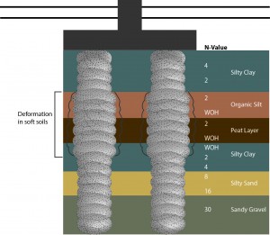
When RAP elements cannot control settlement adequately in soft soils and you have a stiffer soil layer below the soft soils.
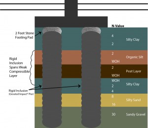
They are stiff Ground Improvement elements that consist of aggregate mixed with cement or grout, or elements made of plain concrete. The elements are stiff enough to transfer the stress from a slab, footing or embankment load through soft soil layers down to a firm soil or weathered rock layer.
There are many ways to create a rigid inclusion. For the last 10 years GeoStructures has been using a variety of rigid inclusion elements to meet project requirements including:
CTA – Cement treated aggregate compacted in Geopier GP3® elements
Cement Grouted #57 Stone – installed using Impact® Pier displacement technique
Cement/Sand Grout and # 57 Stone – installed in Impact Pier elements
Concrete – GeoConcrete™ Columns installed using Impact Pier Displacement Technology
“One type of Rigid Inclusion does not fit every project”
By utilizing a variety of stiffnesses you can match project requirements with the most economical solution. In fact on many jobs a combination of Rammed Aggregate Pier elements and Rigid Inclusions is the most economical solution. The key items to consider in a performance specification are to make sure the rigid inclusion meets both the geotechnical and structural requirements for the project.
Geotechnical – confirm that the element has sufficient bearing and skin friction to transfer the proposed structural loading from a footing or embankment through a soft soil or organic layer down to a firm soil layer.
Structural – Confirm that the element has sufficient compressive strength based on the applied load so it has sufficient factor of safety in compression per ACI codes.
Support of Spread Footings with heavy column loads when the soil strata below consists of thick soft soil layers or organic soil layers overlying a dense soil layer.
■ Case Study: Residence Halls at Howard University Washington, DC Use of grouted Impact® pier elements founded in dense Coastal Plain sands and gravels to support footing loads up to 1800 kips
■ Case Study: Hershey Medical Center Parking Garage Hershey, PA Use of CTA Geopier® elements founded on limestone to support column loads up to 1900 kips.
Support of Heavy Floor slab loads (600 to 1200 psf) when the soil strata consists of soft organic soils overlying dense sands.
■ Case Study: Seafrigo Warehouse Elizabeth, NJ Use of grouted Impact pier elements to span across a organic silt (OH) and peat layers (PT) overlying a dense sand for support of 1400 psf floor slab loads for a refrigerated warehouse for frozen calamari.
Support of MSE Walls or tall embankments overlying thick soft soil or organic soils overlying a dense soil layer.
■ Case Study: 11th Street Bridge Abutment Embankments Washington, DC Use of GeoConcrete™ Columns to support a LTP and 35 foot tall MSE wall.
RIC is a process where loose subsurface soils are improved using an excavator-mounted 7.5 ton hydraulic hammer. The hammer is rapidly raised and lowered onto a 5 ft diameter plate, which densifies the soil, in-place, without the need for undercut and replace. The average compaction point is hit 40 per minute.
One advantage of RIC is that the drop height and number of blows can be varied based on the soil conditions. Through a test program, we will work with the Geotechnical Engineer of Record (GER) to determine the appropriate improvement criteria and RIC set-up for various areas of the site. For a site with a mixed soil profile and varying thicknesses of sand and clay, the ability to accurately control the amount of energy delivered to the ground is critical as it allows one to improve the loose overlying loose soil without liquefying the fine grained soils below – providing more uniform compaction.
Sands, gravels, silts, sandy clays, and debris fills have been successfully compacted with the RIC.
Usually not. A water table depth of 4 to 5 ft below the ground working surface is ideal when compacting clean sands and gravels.
Depending on the existing soil type and condition – improvement to depths of 20 ft can be achieved.
Vibration, measured in terms of peak particle velocity (PPV), has been observed to attenuate to below 2 inches per second (ips) at a distance of 30 ft from the RIC impact point. A PPV of 2 ips or less should not be a cause for concern for most modern structures.
The RIC compactor is mounted on a CAT345 excavator so that moving around the site is easy. The compactor consists of a 7.5-ton weight falling approximately 36 inches onto an anvil in contact with the ground at a rate of approximately 45 blows per minute thereby compacting approximately 800 sf of area per hour. Onboard diagnostics equipment allows the compaction effort to be stopped when optimum compaction has been achieved.
Use of RIC will result in an increase in soil density, stiffness, and angle of internal friction as measured by an increase in SPT N-value, CPT tip resistance or other means of insitu test. The recommended approach is to determine what level of improvement is desired and discuss that required improvement with your technical representative for feasibility. For example, a 2-story commercial light industrial structure is to be constructed on a site underlain by up to 10 ft of existing sandy fill soils. SPT N-values range between 4 and 8 blows per foot (bpf) in the fill. The geotechnical engineer’s correlation between SPT N-Value and soil stiffness for footing settlement analyses indicates that an average N-value in the fill needs be 10 bpf. The geotechnical engineer would perform settlement analyses using the foundation sizes and loading provided by the structural engineer to confirm that the footings will perform acceptably if the fills are improved to 10 bpf. A review of the borings logs indicates that this level of improvement is achievable with RIC. The geotechnical engineer would then complete his or her report with a recommendation that RIC be used to compact the fills in place and that an N-value of 10 bpf will be required.
Providing the building area, project location, and geotechnical engineering report to your RIC technical representative will allow him or her to assess your project for feasibility and develop a budget cost for RIC.
RIC is the right answer when:
■ Over-excavation and replacement is not feasible due to environmental or practical reasons
■ Safety is an issue (no weight falling from great heights)
■ Vibrations need to be managed (< 2 ips at 30 feet)
■ Specific levels of improvement are required
■ Compaction energy needs to be carefully controlled
MSE walls are constructed with discrete facing panels with ¾” open joints on all sides, making them very flexible structures that can accommodate differential settlements up to 1% along the wall face. Where foundation soil conditions result in greater estimated settlements, the use of precast slip joints may be used to provide even more flexibility to the system.
MSE walls are constructed with ¾” open joints backed with geotextile around all panel edges, making them free-draining and accommodating to partially submerged and rapid drawdown conditions. To facilitate the free-draining nature of the walls, open-graded stone backfill, #57 or #3 stone, which has a very high permeability is typically used as wall backfill which allows for rapid relief of pore pressure for walls subjected to rapid drawdown conditions. Hydrostatic pressures and effective unit weights are considered in the internal and external design of submerged MSE wall structures subject to rapid drawdown so the number and lengths of reinforcing strips are designed to accommodate both static and rapid drawdown design conditions.
It is generally recommended to maintain a minimum 1.5 ft of clearance between the edge of bridge abutment piles and the back-face of the MSE wall facing panels. Where drilled shafts are utilized, the greater of 3 ft or one shaft diameter of minimum clearance is recommended. These criteria provide the necessary clear space to achieve proper compaction of the reinforced backfill in this area, and adequate distance to skew the soil reinforcing strips around the deep foundations.
For applications where increased shear resistance is required — for example, global stability of MSE walls or embankments and stabilization of landslides — RAP elements can increase the composite shear resistance. With measured friction angles of the constructed element ranging between 48 and 52 degrees, RAP elements provide significant increases in shear resistance and afford increases in the factors of safety for stability. For more information, please see Technical Bulletin No. 5 on RAP Systems, Shear Reinforcement for Global Stability.